Beam Deflection Calculator — Loads & Diagrams
Combine point and distributed loads on a simply supported or cantilever beam. Explore deflection, shear, bending moment and reactions in metric or US units.
Maximum beam deflection
At 2 m from the left support · 4 m simply supported beam
Elastic analysis · constant stiffness EI · loads entered below
2. Applied loads
Positive = downward; negative = upward. Positions are measured from the left end. Include self-weight as a distributed load if needed.
Up to 12 loads. Results update as you edit.
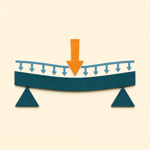
Arrows show load direction and position; their lengths do not represent force magnitude. Detailed loads are listed above.
- Left reaction · upward positive
- 5 kN
- Right reaction · upward positive
- 5 kN
- Largest absolute moment
- 10 kN·m
- Deflection / span
- 1 / 480
Drag the slider or use arrow keys. At a point load, shear is reported immediately to its right.
Deflection
Downward positive. Vertical displacement is exaggerated to show the shape.
Shear force
Positive shear is plotted above the zero line. Vertical jumps mark point loads.
Bending moment
Positive = sagging; negative = hogging. Each diagram has its own vertical scale.
How this beam calculator works
The calculator adds the effects of point loads and uniform loads over any part of a single span. It finds reactions from force and moment equilibrium, integrates the bending moment to obtain rotation and deflection, and searches for stationary points between loads to locate the maximum.
Assumptions, signs & formulas
The beam is straight, prismatic and linearly elastic, with constant E and I. Euler–Bernoulli theory assumes small deflections and neglects shear deformation. Supports are ideal pins/rollers or a perfectly fixed left end. This is an elastic analysis, not a strength, stability, connection or building-code design check.
For a rectangular section, I = bh³/12 about its centroidal horizontal axis: h is the depth in the direction of bending. The dimension helper uses ideal sharp-corner geometry for rectangular tubes; rounded corners and production tolerances are not included. Use manufacturer section properties for rolled or hollow sections when available.
Reference cases: a simply supported beam with a central point load has δ = PL³/(48EI); a full-span uniform load gives δ = 5wL⁴/(384EI). A cantilever with a tip load gives δ = PL³/(3EI). Loads combine by superposition.
Positive applied force and deflection point down. Positive reactions point up; positive moment is sagging. The fixed-end reaction moment is counterclockwise positive. A negative support reaction requires a hold-down capable of resisting uplift.
No self-weight, safety factor or load combination is added automatically. The deflection/span ratio is descriptive; the applicable limit depends on the project.
Reference: FE Reference Handbook — mechanics of materials and beam formulas.
For a hollow steel section and a preliminary stress comparison, use the rectangular tube load calculator.